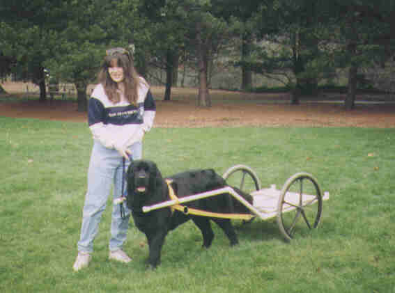
The advantages of the PVC cart are that it is extremely light weight, which is great for smaller or younger dogs. I built this one as a training cart, but still use it even for cart rides for smaller children (I bolt-and-wing-nut a small plastic lawn chair to the cart bed, with a nylon web safety belt). The major disadvantage is that it is relatively fragile; if a large dog panics getting up, he can easily snap the shafts. They can be repaired or replaced, of course.
This cart is made from standard Schedule 40 1" PVC plumbing pipe and fittings with PVC glue at the fixed joints. (Schedule 20, the cheaper version, is far too fragile for the task). The shafts and the optional back (not shown on the plans) are not glued to the base fittings. Instead, like the wheels and axle, they slip into place and are secured either by linch-clips directly, or by linch-pins with linch-clips securing them
The enclosed plans show a bottom view of the cart bed and a side view
of one of the two shafts. They do not show the optional back or the wheel
and axle assembly, which I will describe below. They also do not show the
cart floor, which is just a ¼" plywood piece attached to the bed
with #10 round head machine screws (all the way through the pipe and fittings)
with washers to take up the spaces between the pipe and the floor where
there is no fitting. In other words, the washers make up for the missing
fitting thickness between the floor and the PVC pipe. I put the floor on
top of the pipe to result in a smooth surface.
Parts labeled "a" are T-joints. With the optional back, the parts labeled "b" are also T-joints, but they can be replaced with right-angle fittings if you're not going to use a back. Parts labeled "c" are 90 fittings which support the back (which is just a U shape made with three lengths of pipe and two more 90 fittings, so that the legs come down and meet the upward-facing 90 fittings from the base).
Parts labeled "d" are 45 fittings. There are four - two at the front end of the base to accept the shafts, and one at the bend of each shaft
I made my cart 24" wide. I find that it has great stability with a base this wide , but it's easier to pass a draft test with a narrower cart (18" or so) - as long as your cart doesn't tip over. With a low center of gravity (put your weight flat on the bed of the cart), tipping over should not be a problem as long as you don't hit a tree root too hard!
Cut the lengths of PVC to achieve the spacing indicated in the plans. The dimensions given for the two pieces which make up each shaft are cut lengths, but those in the cart bottom are a little trickier: the 3" dimensions are cut lengths; the 13" and 26" dimensions are center to center (as is the 24" width). As I recall, the 1" fittings use up either ¾" or 1" of the end of the pipe; find out which, and adjust your lengths accordingly.
Before you do any gluing, figure out how you are going to affix the axle, as discussed below. More than likely, you will want to drill a ½" or 3/8" holes in each middle T fitting (a' in the diagram) with the axis of the hole running in the center of the center of the side fitting. In other words, the holes should be drilled so that a rod of the correct diameter for the wheels can pass through each T fitting wall (a') through the center of the central PVC cross-member of the cart base. There are a variety of ways to do this. If you can find PVC pipe which has the correct inside diameter ( ½" PVC pipe marketed for lawn sprinkler systems, and sold in many home improvement stores will, with some sanding, fit inside 1" Schedule 40 PVC pipe), a short length of that material placed in the side port of the T fitting will correctly guide a ½" bit through the wall of the fitting.
In any case, once you've drilled the hole in the central T fittings, assemble the base with all parts but "d" fittings glued in place. I assembled the cross pieces to three T fittings first, glued those three together to form one side (pressing the cross pieces to my table saw top to be sure they'd end up in the same plane), then glued the remaining side to the ends of the cross pieces. Then I glued the 3" stubs to each open T end. I glued together the back piece, and dry-assembled it to the 90 fittings so that they were properly aligned to the back during gluing. The trick is to work up some speed so the glue doesn't set up on you before you push everything home.
If you haven't worked with PVC before, experiment on scraps and extra fittings. You need to swab glue on both pipe and fitting, then press them home and hold them fully seated for 30 seconds. To be safe, buy and use PVC cleaner on both before applying the glue. It's typically a purple solvent which cleans the mating surfaces for best adhesion.
The shafts are unremarkable, as there is no need to worry about rotation as long as you wait until they are assembled before drilling for the two eye-bolts (¼" by long enough to penetrate). I glued dowels in each end (the open end of the short piece, and under the cap of the long (front) piece). This gives the PVC more strength where the linch-pin keeps it from twisting at the front end of the cart, and where the eye-bolt penetrates at each end so it won't collapse when you tighten the nut.
Setting the front 45 fittings is one of the trickier steps. They need to be angled in so they can hold the shafts one foot higher than the cart bed and 16" from each other, with the 16" gap centered at the front of the cart. Although at this point the shaft can turn in the fitting and the fitting can turn on the front of the cart, there is only one alignment of all four pieces (both shafts and both 45 fittings) which will produce parallel shafts (parallel to each other and to the plane of the cart bed) with the shafts 16" from each other. What I did was put the cart bed on a level surface (a floor will do, but watch out for the glue!) with the 45 fittings not yet glued, then affixed the shafts (also not glued). I fiddled until I had the position I wanted. I found that because the PVC will sag a bit, I had to support them at the front end. With straight edges at each cart bed edge, I could center the support, and align the shafts by measuring the support (ideally a 25" by 12" piece of scrap, with a mark at center and at 8" either side of center). I hope this is reasonably clear.
When you get the shafts and 45 fittings in the correct alignment dry (without glue), carefully mark each with a sharp knife - scribing both the shaft and the stub on the other end of the 45 fitting, and the fittings themselves. Then mark the scribe lines with a marking pen or otherwise so you can find them quickly and easily during gluing.
Then glue each 45 fitting to its stub at the front of the cart, carefully aligning the scribe lines on the fitting to its mate on the stub, so as to duplicate the alignment from the dry fitting. When the glue sets up firmly, insert the shaft into its 45 fitting with the scribe lines aligned. Recheck your spacing to make sure you still have the shafts 16" apart and parallel to each other and the ground. Then drill through both the fitting and the shaft for the linch pin (or clip).
The point here is to be able to insert a pin which will keep the shaft in the fitting, but will allow you to remove the shaft when you take the cart apart. I wouldn't recommend giving up and gluing the shaft in place, as it will almost certainly result in breakage when you are moving the unwieldy combination of shafts and cart into your car or van or truck. I think it important to drill for the pin as close to the center of the fitting and the portion of the shaft which is within the fitting to minimize the weakening which removing material surely causes. I've been using the cart for a long time now, and I have not had any breakage where the shafts connect. Remember that I have a wood dowel press-fitted into the end of the shaft to keep it from collapsing and to make it stronger where the shaft joins the cart.
My answer to a linch pin for the shafts is a ¼" hex-head machine bolt selected so that its unthreaded section is long enough to pass through the fitting and protrude at least 5/16" past the other side. I cut off the threads, and slightly chamfered the remaining end of the bolt to make it easier to pass it through both walls of the fitting and the end of the shaft. Then I drilled a small hole in that end to accept a small linch-clip (see the diagram for the profile of a linch-clip, which you can get at any good hardware store). To assemble the shafts to the cart, I align the shaft in the fitting, make sure visually that the holes are exactly in line, insert the linch-clip (from the bottom up), place a ¼" flat washer on the pin, and finally secure the pin with the linch-clip until I'm ready take the cart apart. I needed to sand down that end of each shaft to make it easy enough to insert and remove the shaft from the fitting, as they are too tight for comfort otherwise. Don't take off too much material. Water (spit, actually) is a great lubricant to aid insertion and positioning during assembly.
The same arrangement works for securing the back to the cart bed.
I've built three carts (counting a PVC training rig which is just wheels, two shafts, and an axle). On each, the really challenging part was the wheel and axle part. I've done it various ways, and it doesn't matter which cart is which - in each case, my solution depended on what wheels I started with. My first cart (the metal one I still use) has Troy-Built Tractor wheels. They are heavy (25 lbs) with ¾" shafts. I think they are too heavy for the PVC cart, and might even break it. The PVC cart has used 24" wheel chair wheels which take a ½" axle. (If your wheels are much different than 24" in diameter, you may have to alter the shaft dimensions to get them at the right height for your dog). To accommodate this, I used ½" hex head machine bolts bought to get the longest possible unthreaded section of shaft, with the threads cut off and the end filed smooth. I then inserted lengths of ½" PVC lawn sprinkler pipe (threaded nipples are available) into the 1" PVC pipe (some sanding was necessary) to achieve a ½" hole well into each side of the central T-fitting (a' in the diagram). I drilled a ½" hole from the inside of the T fitting, as described above. I inserted the hex-head axle through the wheel and into the cart, then drilled for a linch pin through the central member of the cart and the end of the axle. In use, a linch-clip (much larger than those which secure the linch pins at the ends of the shafts and back member of the car) to secure the axle.
A much easier arrangement is to buy a three foot length of unthreaded rod, drill near one end for a linch-clip, assemble the rod with a washer and linch clip on one end, both wheels, and the cart bed in between. Depending on your wheels, you may or may not need washers between the cart and the wheel. Then mark for a second hole so as to secure the wheels against the cart (with room to turn supplied by those washers, if necessary). Drill the second hole, cut of the remainder of the axle, and file it smooth.
The eye-bolts which are shown at the front end of the shaft and near
the cart end (with enough distance from that end to clear the fitting on
the cart which accepts the shaft) are ¼" eye bolts long enough to
penetrate the cap on the front, with a nut and lock washer. I cut off the
excess and peened the threaded end to make sure the nut didn't come off.
The distance between the two eye-bolts on each shaft (41½") is right
for our harnesses. If you get a Siwash or any other harness, you will have
to alter these measurements to fit your harness.